
Are you ready to take your circuit design from the schematic stage to a fully realized printed circuit board (PCB)? This article, PCB Design Basics: From Schematic to Board Layout, will give you all the knowledge and skills you need. You’ll learn how to turn a set of specs into an efficient layout that meets safety standards and fulfills your creative vision.
By the end of this article, you’ll have all the tools necessary for success in every step of PCB design. So without further ado, let’s dive into understanding what it takes to create reliable circuits with careful attention to detail.
Generating the Gerber Files
Generating Gerber files is one of the most important steps in PCB design. Gerber files are a type of vector file that can be used to produce a printed circuit board (PCB).
They contain all the information necessary for producing an accurate and reliable PCB, from the schematic to the physical layout. The process of generating these gerber files involves taking data from various sources such as CAD software or a schematic capture program, and transforming it into readable code. This code is then used by fabrication companies to produce your final board design accurately and quickly.
It also ensures that all components are placed correctly on the board and any errors have been taken care of before production. Generating gerber files can seem daunting at first but once you understand what goes into them, it becomes easier with practice.
With patience, attention to detail, and good quality inputs, anyone can create excellent boards with great results!
Fabrication and Assembly Processes
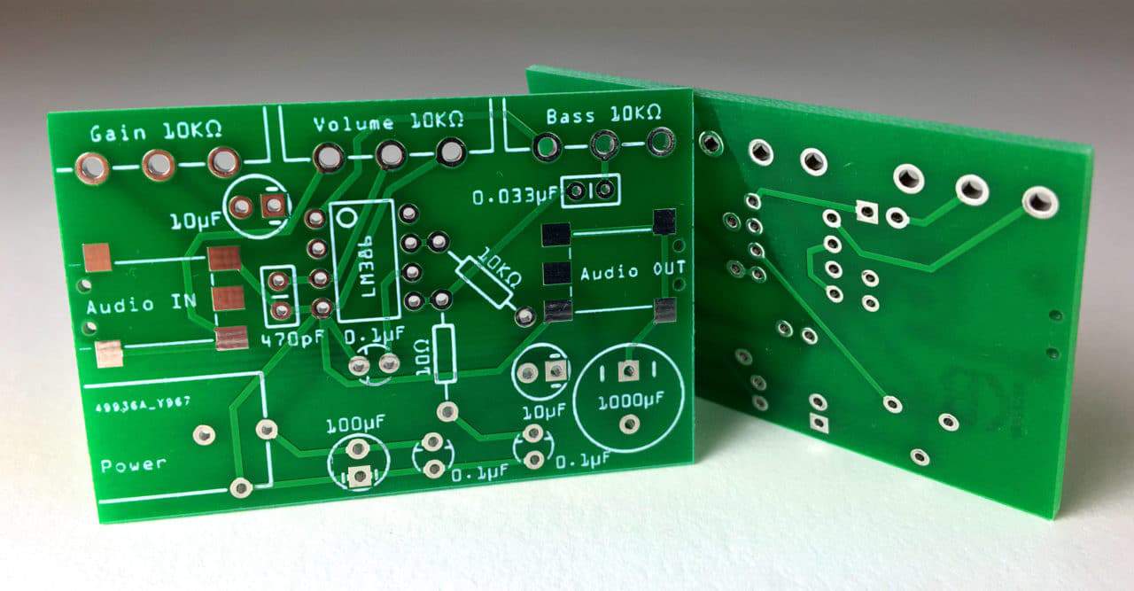
Source: circuitbasics.com
Fabrication and assembly processes are an essential part of the PCB design process. To ensure that your board is ready for production, it must be designed to meet specific fabrication and assembly requirements.
During the fabrication stage, components are soldered onto the board using specialized equipment such as wave solder machines or reflow ovens. During the assembly phase, additional parts may be added to further customize your PCB layout.
For example, pin headers can be used to connect external devices and switches can be installed for user input control. Additionally, extra eyelets or rivets may need to be added depending on usage scenarios.
Once all these steps have been completed, a final inspection is performed before packaging begins to guarantee quality control standards have been met before shipping out your finished product!
Conclusion
PCB Design is a complex process involving many steps. However, the basics remain the same: from schematic to board layout. Each step of the design process requires careful attention and consideration to ensure that the PCB will function properly and perform as expected.
With a clear understanding of these basic concepts, designing custom PCBs can be an enjoyable and rewarding experience for any engineer or hobbyist alike.
Source: resources.pcb.cadence.com


